
Firmware
Firmware is usually the part of the project that takes the longest, so whatever we can do to accelerate this process will accelerate project completion.
initial planning
We like to start with a product requirements document (PRD) so we can adequately assess the key risk areas in the firmware. Does it need to be fast? Does it need to be low power? Identifying any key constraints like these will help us de-risk the product.
a layered approach
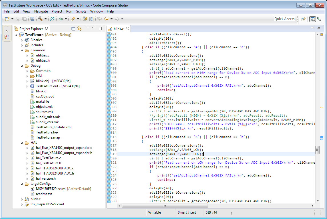
We write a lot of firmware and have found that a structured approach works the best. Even for very small projects we like to keep the hardware access libraries (HAL) in its own self-contained files, separate from the application. On one project we had to support the same firmware running on about a dozen different microcontrollers. So for this we got really good at porting code. One thing we’ve learned is that it’s very important to have consistent and clear documentation. We like to follow the Doxygen format for code commenting. Rarely do we generate the Doxygen output but at least this gives us a consistent format.
Remote Firmware Update
Once the requirements have been defined, we can proceed with hardware design, including:
component engineering
First, we determine what key components we’ll need in the design. We select components based on:
Performance
Cost
Availability
Manufacturability
If we don’t already have the component in our library (and we have a lot, several thousand) then we will build the component in our system, including schematic symbol, link to a supplier, create PCB footprint and add 3D model. The last part is important - the 3D model allows us to verify the footprint with the actual part. Most errors on boards are incorrect footprints, so we follow the IPC guidelines in designing footprints.
Schematic Capture
I always thought this was a funny term for drawing the schematic, as if the schematic was running around in the wild and we had to trap it somehow. This step entails doing the calculations on the design and drawing the schematic diagram. There are different philosophies about how much information to put on the schematic, but we will generally try to put all calculations and links to notes on the schematic so they’re easy to find and verify later. This step is really “where the rubber hits the road” and is the key to the rest of the design. We will also compare our design with the chip manufacturer’s reference design and ask them questions as needed.
PCB Layout
We will use the completed schematic to layout the components on the board. We will work with your mechanical designer to identify the mechanical constraints (board shape, component keep out areas, etc.) Then we will place the components and route the connections. Once the routing is done then we’ll take a look at the board and see if there are any more test points or labels that would be useful.
manufacturing documentation
After the board is complete we will create the manufacturing documents. We work closely with the contract manufacturers to supply them with the information they need. We are somewhat passionate about manufacturing drawings and have spent many hours researching optimal notes for PCB fabrication and assembly. See blog post on this topic.
Firmware
Oftentimes the firmware takes longer than any other step. For this reason we’ll try to start the firmware as soon as possible, preferably before the boards are done.