Manufacturing Test
Studies have shown that the sooner you find an error, the lower the cost to fix it. If you are building a product to be produced in volume then you will need some type of manufacturing test to catch any errors before shipping. Manufacturing test systems range from basic manual systems, to fully automated systems which minimize labor. Manual test systems are cheaper to design but incur more labor and hence a higher test cost per device. Automated systems are more useful as volume increases, since it lowers the test cost per device.
Test plan
The first step is to create an outline of the test requirements and capture it in a document called a test plan. There are many versions of the test plan (see IEEE-829 for one example) but this document typically includes:
Why we test (quality / regulatory compliance / safety etc.)
What to test (coverage)
How to test (methods)
Apparatus (hardware/software required)
Verification (testing our tester)
Target test cost / time
why test
“If you don't know where you're going, any road will take you there”Before getting into the details, we need to answer why we’re doing the testing. Is it to ensure there are no errors? To comply with regulatory agencies? To prevent the product from causing death or dismemberment? These answers can have a huge impact on the test plan and need to be determined before going any further.
Test coverage
“Only test the features that you need to work”Determining what to test is as much an art as a science. Under-testing means that there is risk that a device may fail because we didn’t test something. Over-testing will burden the manufacturing process with unnecessary cost and time. The theoretically ideal way to determine coverage is to start by testing everything, and then reduce coverage statistically, eliminating coverage for sub-systems that never fail, or where the cost of testing exceeds the cost of failure. However, in reality, that rarely happens: once the test system is up and running, none of the stakeholders want to reduce test coverage.
Test method
Once we’ve determined what we need to test, now we determine how to test it. This includes what steps the technician will perform to carry out the test. In a manual test setup this list will be very long and detailed. In an automated test system the method may be as simple as “press the space bar to start the test.” For example when measuring quiescent current, a low volume approach would be to have a technician connect the device to an ammeter, read the current, and write it down. A more automated approach would be to have a test fixture power up the device, measure the current with a custom circuit, and then record this value in a database.
When determining the test method, we also need to consider how to troubleshoot devices that failed the main manufacturing test. This will typically be a more detailed, labor intensive test method where a technician can examine more signals.
apparatus
We need to determine what equipment we’ll need for the test. See the next section for what comprises a typical test station.
test station verification
You’ve finished your test station, your Golden Boards are passing every time, so you’re done, right? Wrong - you need to verify that it detects all the errors that you want to detect. This is called test verification - verify that the system detects passes and failures. For this you need a collection of “known bad” boards. This is an assortment of boards, one with every possible failure mode. These are very valuable to the test station designer - I guard mine like Gollum guards the Precious. For example, if you’re testing a wireless sensor that verifies the accelerometer, radio, and button, then you need three different known bad boards - one with each of those issues. We don’t typically test combination errors since once one error has been identified the board fails out anyway. Depending on your production quality, this collection of known bad boards may take awhile to accumulate naturally so we’ll help along the process by carefully butchering a batch of boards. On that accelerometer I mentioned, we’ll have a board with the SPI SCLK cut, one with MOSI cut, one with the interrupt line cut, and one with the sensor removed altogether. The goal is to ensure that all of these errors are detected. To make life easy I label each known bad board with a label showing the error code.
If you’re measuring current then you’ll also need a batch of boards with a known current draw. The easiest way is to use a precision resistor. For example, if you’re powering your device with 3V and want to measure down in the micro-amperes then you’ll need to populate a 1 meg ohm resistor on a board to test.
Testing Station
Once the test requirements have been defined, we can proceed with designing the testing station. The test station typically includes multiple sub-systems:
Test Fixture
Physically holds the printed circuit board being tested
Single, multiple, or panel-level fixtures are used
Electronic Interface
Programming firmware, typically with a COTS programmer
Program serial number / encryption keys
Software
We try to make it easy for the technician: few steps, go/no-go results
Cloud based test result storage
Store test results in the cloud for analysis and safekeeping
Amazon Relational Database Service (RDS)
test fixture
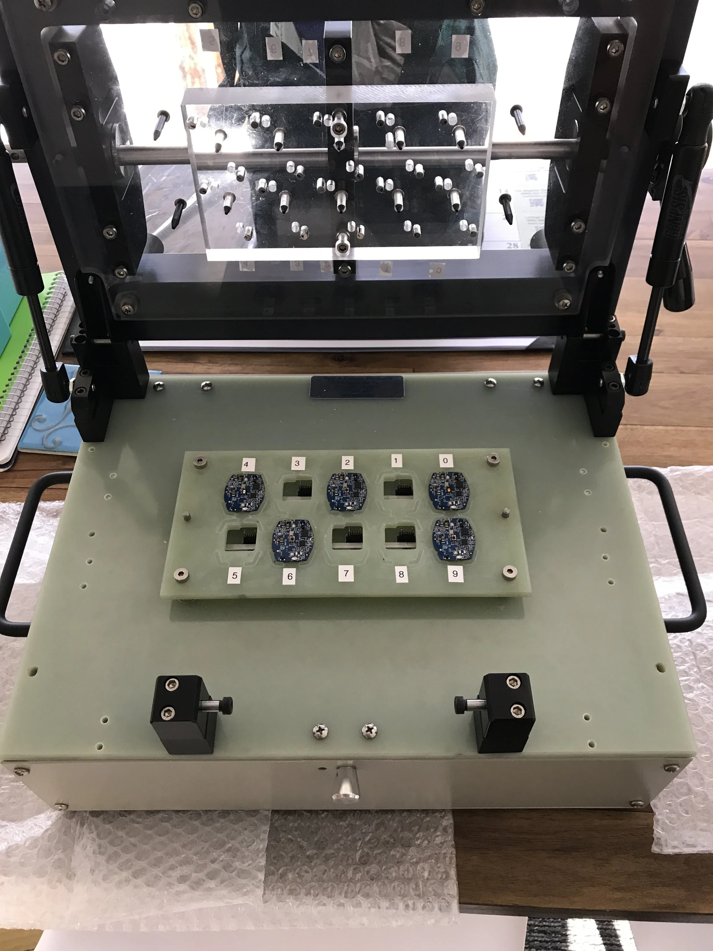
The test fixture holds the PCB in place. It may either be for one board, a few boards, or an entire panel. The image to the right shows a test fixture that can either test individual boards or the entire panel.
Below the test fixture tray is where the custom electronics, programmers, USB hub, etc. are located.
This fixture connects to a laptop computer for command and data logging.
electronic interface
The device under test typically needs power and communications. As part of the test fixture design we will design this connection, incorporating any current measurement circuits or multiplexing. While we try to avoid having to design a custom PCBA for the test fixture, it’s usually required for multi-unit fixtures to accelerate the test and get accurate results.
software
The test software is customized for each product, and may do the following:
Program Firmware
Read barcode label
Program serial number
Device self-test
Device current consumption
Record results in the cloud.
manufacturing documentation
After the board is complete we will create the manufacturing documents. We work closely with the contract manufacturers to supply them with the information they need. We are somewhat passionate about manufacturing drawings and have spent many hours researching optimal notes for PCB fabrication and assembly. See blog post on this topic.
Best Practices
Through the years we’ve learned many lessons designing test fixtures, including:
Test station deployment to the manufacturer
Label everything with client name, and engineer contact information. If there’s any issue you want them to get ahold of you easily.
Make it easy to troubleshoot over the phone. If using a laptop onsite, set up some desktop sharing application that you can use to diagnose issues. And use idiot lights everywhere to show that things are connected, powered on, etc. The time you save may be your own!
Tie it down. Sometimes I’ve seen cables or barcode scanners get misplaced at the CM. So now I’ll zip-tie the cable to the test fixture. It still might run away but it takes more work.
Make instructions with lots of photos. Screenshots, hook up photos, etc.
Label in place - we go through a lot of P-touch label tape when deploying a test fixture because we label everything. On the laptop, label each USB port with what plugs into it (“Barcode scanner”, “Packet Sniffer”, “JTAG Programmer”, etc.) This makes it easy to connect everything if it gets stored in a box or something.
Keep it simple! As simple as possible but no simpler. Try to get it down to pressing a space bar to start, and then getting a pass/fail display on the screen at the end. Don’t make the technician read the tea leaves.