
PROJECT
Gallery
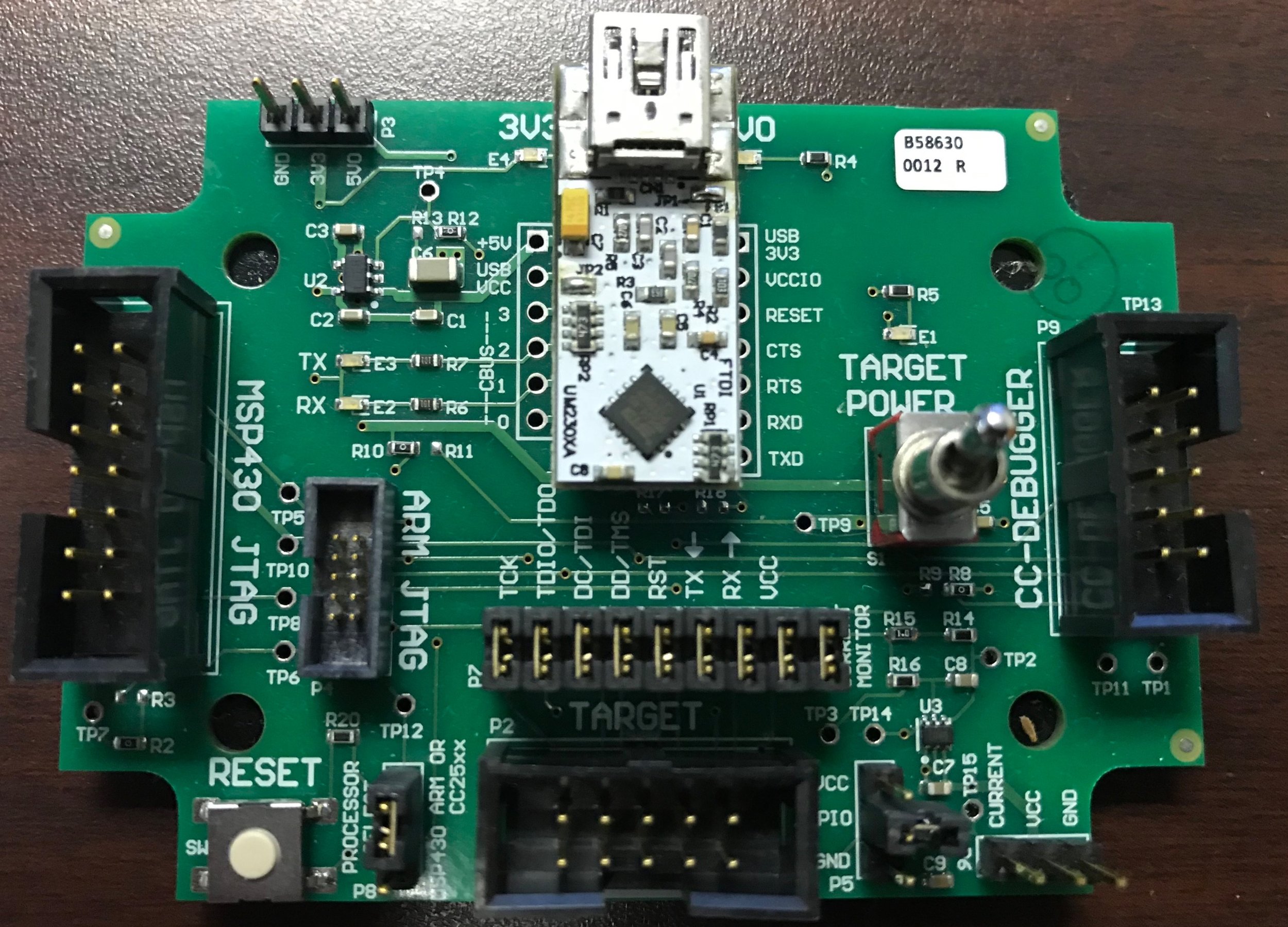
We found that most designs need the same interface for manufacturing test and debug so we built this little programming board. This combines power, serial communications, and JTAG programming into one universal cable. This board acts as the breakout for that cable and also enables current measurement.

This is a high volume wearable device that may be purchased at a Best Buy near you. It incorporates a Bluetooth radio, accelerometer, LEDs, etc. For this project we made several changes to the PCBA which increased the Bluetooth range from 30’ to 300’ while reducing the cost by 10%.

This scope capture is from the Ethernet clock line of a project where we were brought in to get it to pass EMC. Yellow is the signal in the time domain, red is the signal in the frequency domain. On this signal we had to tweak series resistor values to minimize the EMI.
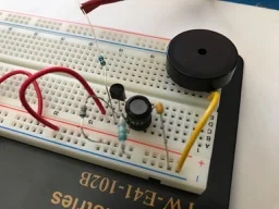
Sometimes, nothing beats a good old fashioned breadboard. We were working on a project that needed a loud alarm. The client had an opinion as to the type of sound that they wanted so we created a little test circuit to drive various speaker elements. This way the client could ensure that the final solution was loud enough for their product. We could have instead provided multiple population options for different speakers but by testing early we were able to identify the preferred component.

This is a photorealistic rendering of a small USB dongle PCBA. It needed to fit within a custom enclosure so we exported a 3D model (STEP file) of the board for the mechanical designer to incorporate into his design. This makes the mechanical integration much easier because we can quickly identify conflicts. You may notice there are many missing components - this is because we originally designed in additional features like USB Tx & Rx LEDs but later omitted them for final production. This also shows our preferred approach to labeling test points with their actual signal names, or a close approximation.
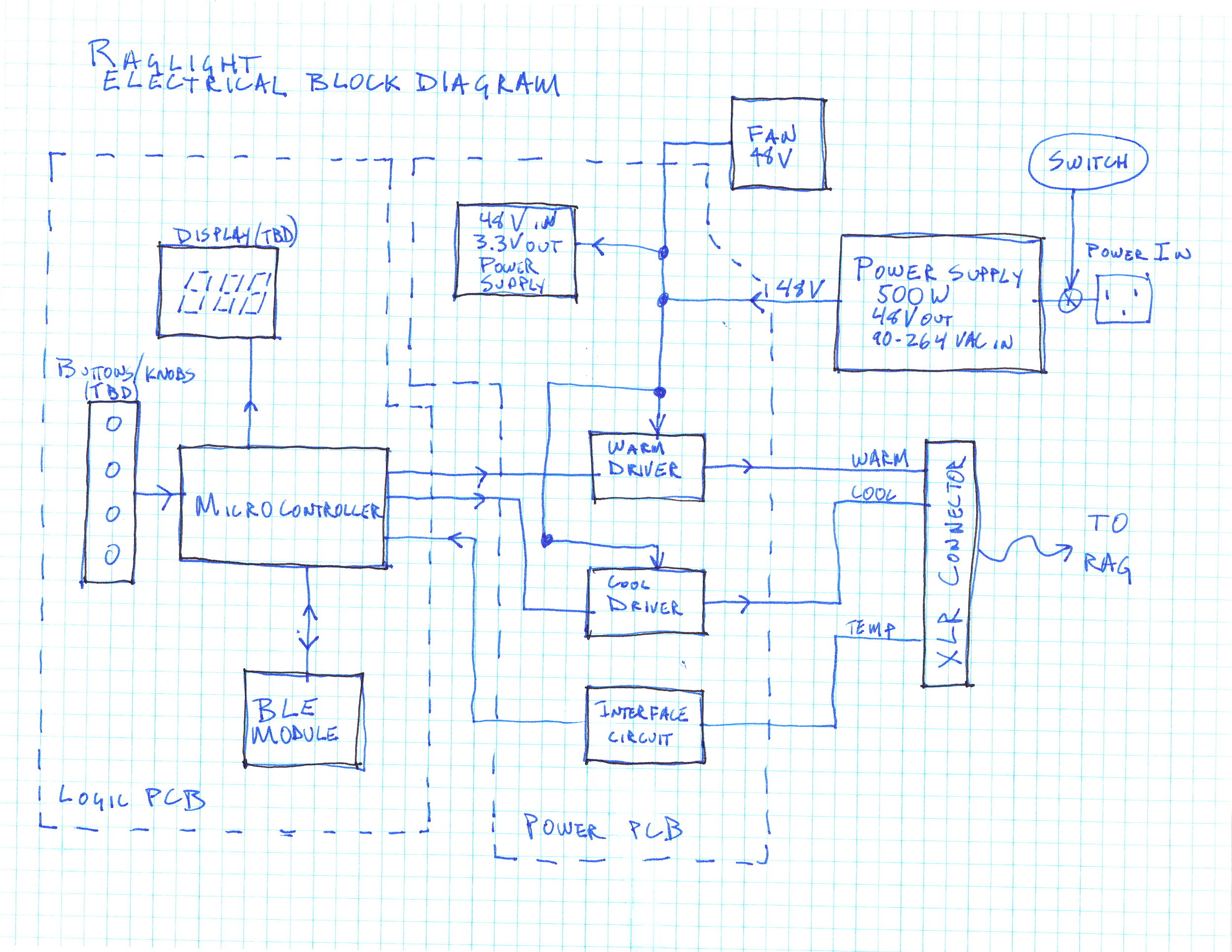
This is a block diagram for an entertainment lighting fixture. It included a little bit of everything: high power LED drivers, closed loop control systems, wireless connectivity, and a few cable harnesses to connect the three different PCBAs. Most of our projects are fast paced with very little time to spend on documentation. So for diagramming we tend to do a lot of hand drawings to convey the point across without getting ensnared in a graphics program. The goal is to communicate the information quickly and effectively.
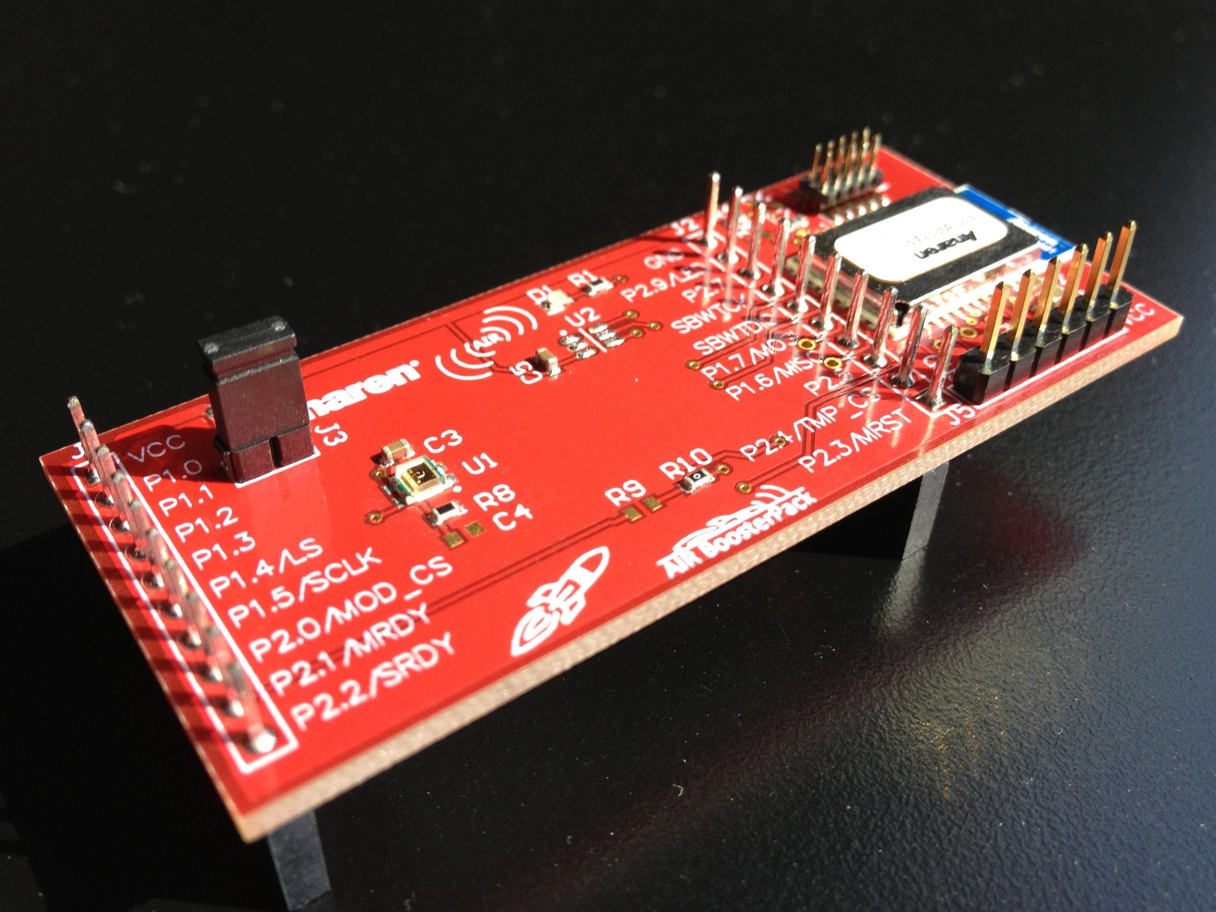
Texas Instruments has a common development board standard called the BoosterPack which allows one board to work with many different microcontrollers. This is a simple BoosterPack for a Zigbee wireless module. We designed this in an extremely short timeframe (including a one-day PCB turn) so that the product was ready for a trade show. The product met the customers timeframe, worked right out of the gate, and made a positive impact at the trade show.

This table is from a cloud based MySQL database and shows the results of a manufacturing test for one product. This is hosted in Amazon Web Services so that the information is always available and we can monitor testing in real time. For most products like this we track when the test occurred, the results, and whether it passed. Test results are used for statistical process control (SPC) by the manufacturer and client to ensure that production does not have any issues. This product uses multiple test stations so we track where the test was run too.

A printed circuit board is made up of multiple layers of copper sheet, from 1 to many. Each layer is a different pattern of copper and may contain ground, power, or signals. The stackup shows how the different layers shall be combined, and is developed based on the product requirements and the PCB vendor’s capabilities. This stackup is from a fairly complex medical device.

Printed circuit boards should have test points to make it easy to test the hardware during development and diagnose issues during production. This rendering of a board shows how we like to implement test points. First, they’re labeled with their signal name. This makes troubleshooting substantially easier since you can find the signal right away. Second, these test points are spaced at 0.100” spacing so we can solder standard headers to them. These headers allow us to leave wires connected without having to manually solder tiny wires to the test points. Finally, the signals are grouped by their function: SPI, power, etc.

Once the schematic is complete and all the footprints have been created, we can start on the layout. The first step of layout is placement. Here you can see the beginning of layout, where we group components according to function. Next we’ll move these groups into position onto the board.
After placement is done we’ll review the board with the mechanical engineer to ensure that there are no conflicts, and then we’ll begin routing.

This product used an FPGA to drive eight (8) stepper motors. There were three boards in the design: a) the logic board containing the FPGA and low voltage connectors, b) the front panel user interface board containing LEDs and switches, and c) the motor drive board containing the high current drivers. We designed all three; this is the motor driver board. In addition to designing the hardware, we also designed a custom anodized aluminum heat spreader for the drive ICs. The product has been on the market, exceeding customer expectations.

When designing printed circuit boards, we usually endeavor to make the board cooler. In this medical project we needed the opposite - to make the board into a heater for a sub assembly above. So we designed the board with a series of serpentine traces. Each of the four heater zones had approximately 10 feet of PCB trace to provide a uniform heating platform. This board was placed under a series of pneumatic pistons. At one point, activating a pneumatic piston would cause a short in the system and the entire system would reboot. The software guys were convinced it was a hardware error. After much investigation we discovered that it was actually a mechanical error: this board was placed against a metal plate and the piston would press the board into contact with the plate, causing the short. We then added a thin membrane to protect the board from the pistons.
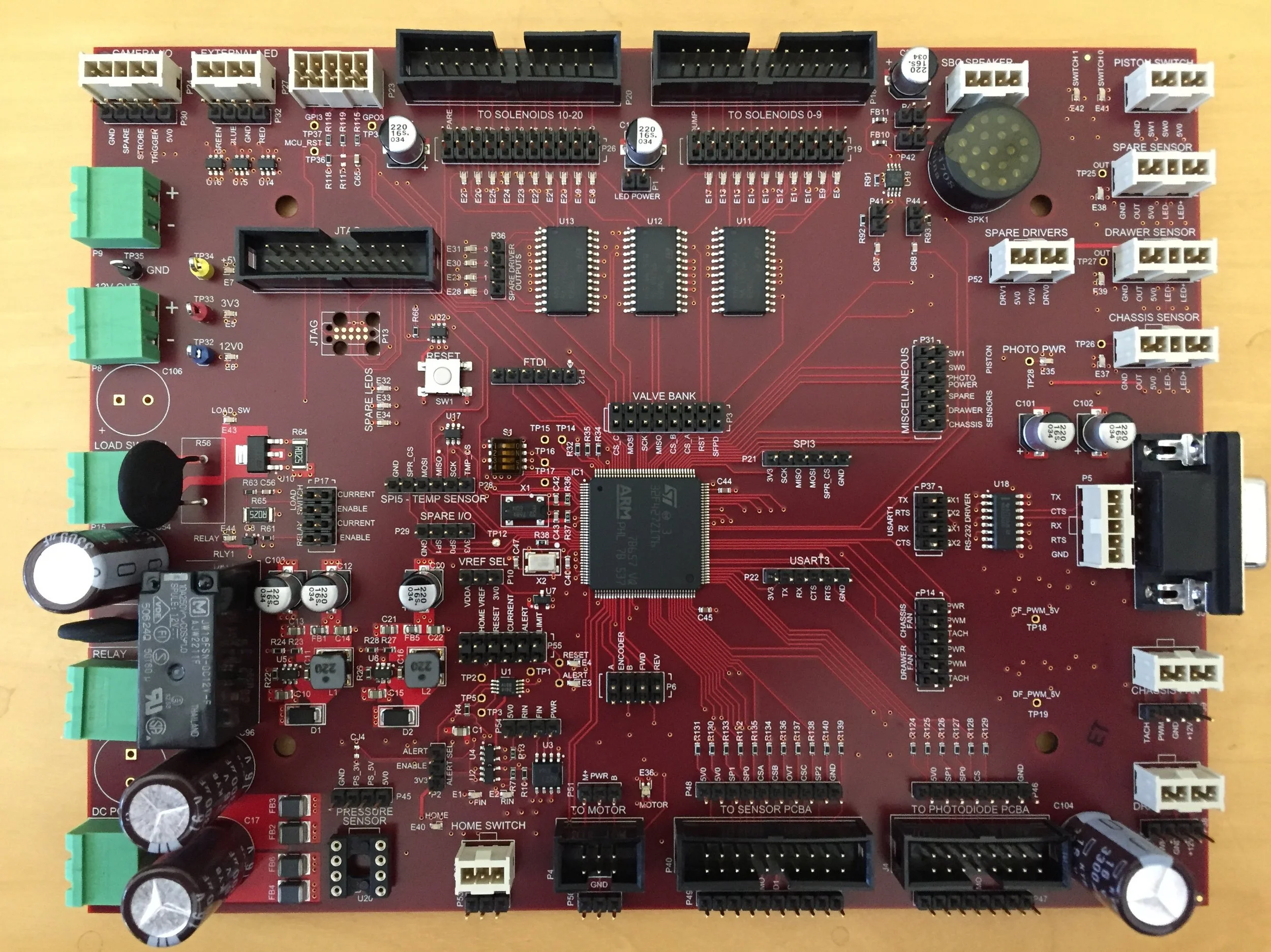
We’ve done a few medical instruments and have refined our architecture along the way. We used to put a processor down on a custom board along with all the application-specific circuitry required. We’d then spend a ton of time debugging the processor and the application specific circuitry. Since then we’ve modified our approach: now we like to use a COTS single board computer or module along with a custom control board, connected via USB. This shows the custom control board which used an ARM to interface with over 50 actuators and sensors.

We are experienced at working with mechanical engineering teams to get motion control systems working. This funny photo shows one way we improvised an encoder wheel during testing. The encoder wheel is attached to a screw drive motor shaft and is used to count the number of revolutions made by the motor. The encoder wheel that the ME designed had too many notches; the little microcontroller could not service the interrupts fast enough. So we prototyped a new encoder wheel in about 5 minutes using materials in our office. If you can guess where that wheel came from you’ll get a prize - email us at the link at the bottom of the page.
iBeacon is an Apple protocol that defines an interface for Bluetooth Low Energy (BLE) beacons. These are used for proximity alerts, geotagging, etc. There’s also the Google Eddystone protocol which is similar. We’ve now built a few different beacons. They’re all very similar, including a battery, a bluetooth low energy radio, and simple firmware to send out a message at a fixed interval. We also have a line of tools to help iBeacon device development that we use when bringing these through production.
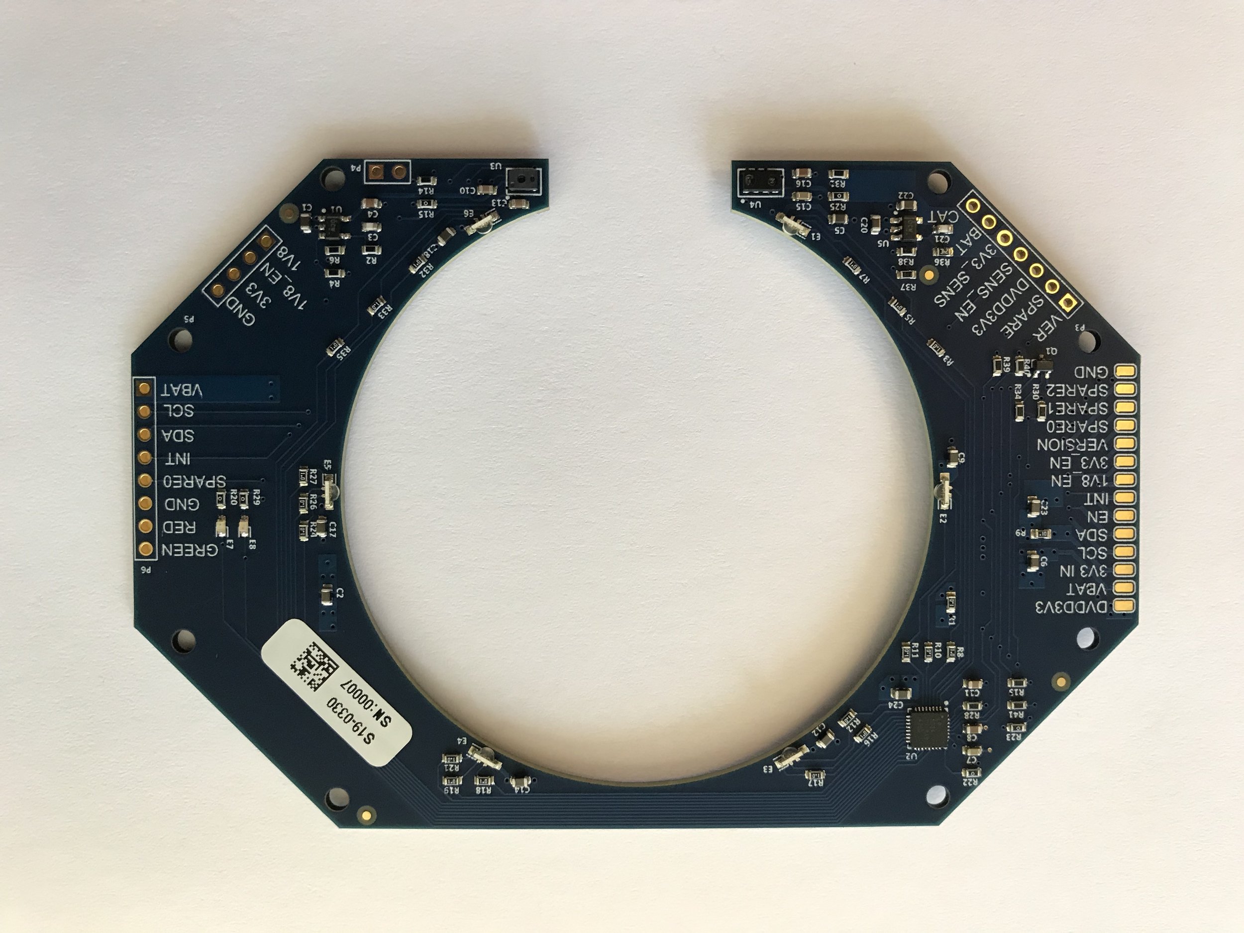
We work very closely with the mechanical engineering team to ensure a smooth integration between the PCBA and the rest of the design. Occasionally this necessitates interesting board outlines such as the LED driver board shown here.
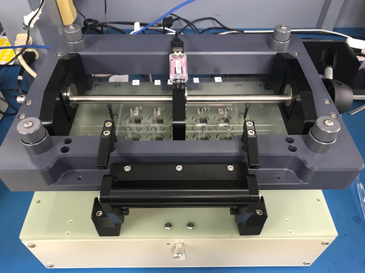
Every PCBA needs to be tested during manufacturing to ensure correct assembly. For high volume products we try to test many units at a time. This photo shows a 10-up board of nails test station for a high volume wearable device available at a Best Buy near you.

As part of our services, we review existing designs, to reduce cost, increase reliability, replace obsolete parts, etc. This image is from an 8 layer portable medical device showing all the named nets used. When this board came to us it was almost un-manufacturable because of overly tight layout. We worked with a board house to reduce complexity and increase reliability.